Dispatcher Center Equipment
Local system comprises equipment and software required for it’s self-contained functioning, including Dispatcher Center (Fig.1).
Fig. 1. Block Diagram of the Dispatcher Center.
Structure of the base equipment of the Dispatcher Center.
- Receiver CTN-9902;
- Local PC Network;
- AVL Systems Software GUARDTrack.
- Receiver CTN-9902
The receiver of a base station has a module structure. The structure of modules of the receiver depends on problems and configuration of a system.
- Full receiver structure:
- 1-8 GSM Receiver Modules CTN-9902/G20 (Option);
- 1-2 ORBCOMM Modems Module CTN-9909/O (Primary and Backup);
- DGPS Communication Module (Option)
- Backplane.
- All modules (Plug-in unit) are established in a Basic Case 3U.
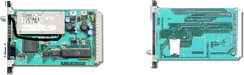
- GSM Receiver Module CTN-9902/G20 features
- Siemens M20 type GSM OEM Module;
- Full functional GSM terminal (DATA, SMS, FAX, VOICE functions);
- Standard RS-232 interface connection (9-pin connector) for PC;
- 64-pin interface connector which includes power and data lines.
- ORBCOMM Modems Module CTN-9909/O features
- “QUAKE Wireless” company ORBCOMM OEM Module;
- Full functional ORBCOMM communicator;
- Standard RS-232 interface connection (9-pin connector) for PC;
- 64-pin interface connector which includes power and data lines.
- NOTICE: The communications protocol of the receiver with the software is open for the end-users of a system.
- Fig. 2. Design GSM Transceiver Module.
|Main Page| |Introduction| |Dispatcher Center Equipment| |AVL System Software| |The Kit of On-board Transport Equipment| | The Kit of On-board Transport Equipment - next page|
(C)opyright Transexpo corporation. All right reserved.